

The SHOT Line: A Subsurface Canal Bypassing Hormuz
A canal beneath the conflict
In watching the body count rise, along with the risk of WWIII in the U.S.'s blockade of the Strait of Hormuz, I offer this concept of an asphalt-lined subsurface oil and gas canal and corridor. The asphalt based tunnel overcomes steel pipeline engineering problems by using an oil based product (asphalt) to move oil in a subterranean canal, along with the increased security and capacity exceeding that of supertankers.

Unlike my first U.S. Patent, Systems and Methods of Insurance Claims Settlement, which benefited the insurance company, this is for peace and goodwill to all.

"Behold, I will do a new thing" - Isaiah 43:19.

- JPB
White Paper: Subterranean Hydrostatic Oil Transport (SHOT) System
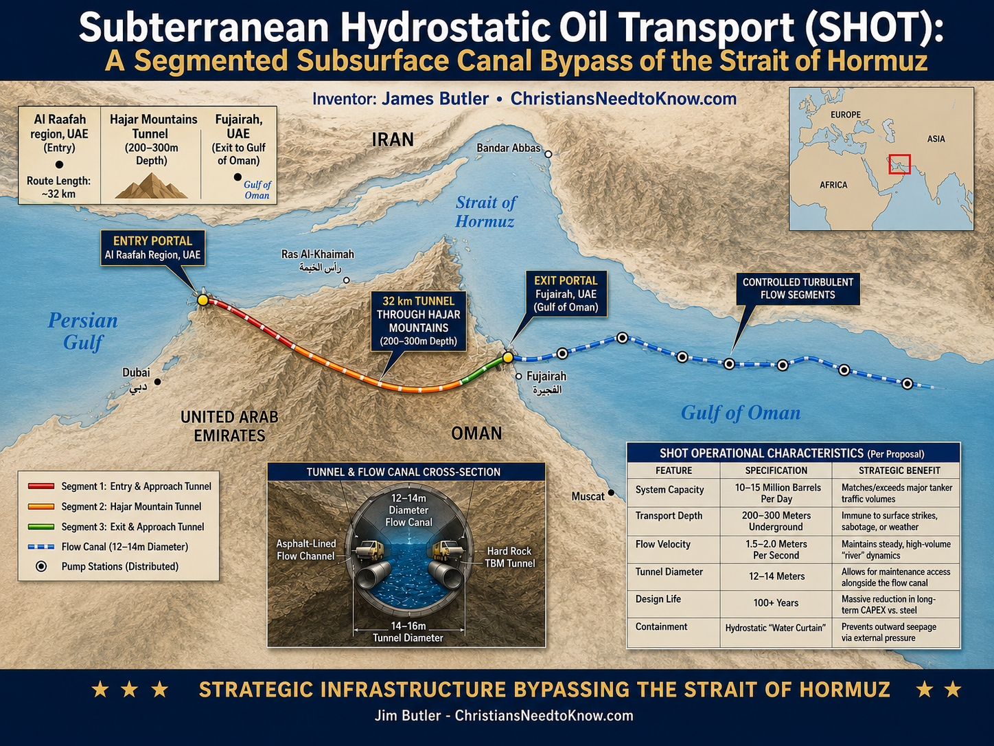
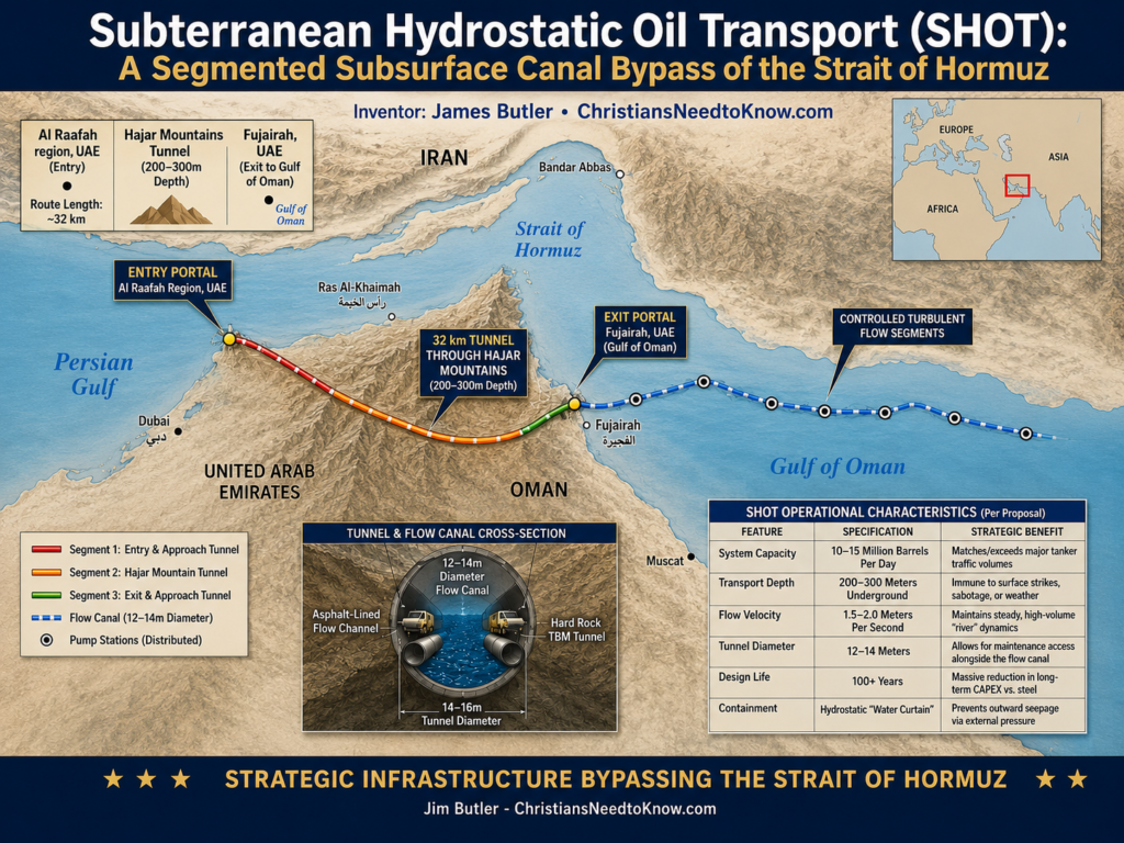
Title: Subterranean Hydrostatic Oil Transport (SHOT): A Segmented Subsurface Canal and Energy Corridor Bypass of the Strait of Hormuz
Inventor: James Butler
Classification: Strategic Energy Infrastructure Concept
1. Executive Summary
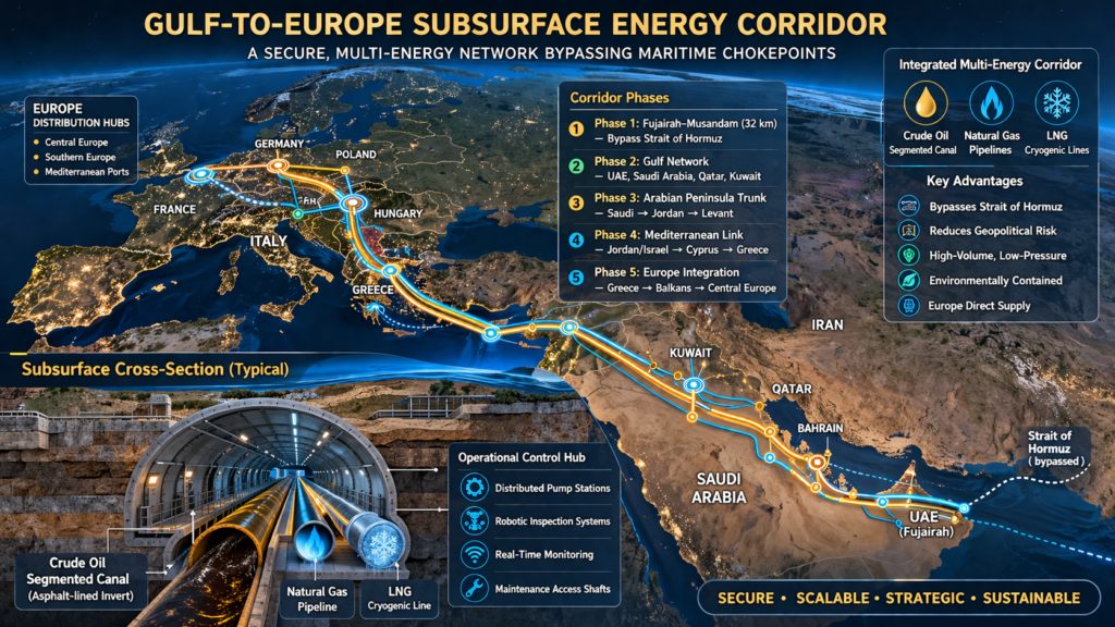
The SHOT system proposes a segmented, subterranean oil canal integrated within a broader multi-energy transport corridor. Designed to bypass the Strait of Hormuz, the system enables secure, high-volume movement of crude oil while simultaneously supporting natural gas and LNG transport within a single underground excavation.
Rather than relying on high-pressure pipelines alone, SHOT operates as a low-pressure, high-volume hydraulic system for oil, combined with independently controlled pipeline systems for gas and LNG.
The result is a layered energy corridor that consolidates multiple transport modes into one hardened, subsurface infrastructure.
2. Concept Overview: Subsurface Canal + Energy Corridor
SHOT is a hybrid system combining:
- A segmented oil canal (primary transport layer)
- Parallel pipeline systems (gas and LNG)
- Shared structural and access infrastructure
The tunnel functions as:
A subterranean energy corridor, not a single-purpose conduit
Key characteristics:
- Segmented, controllable oil flow
- Independent thermal and pressure environments for each energy stream
- Centralized maintenance and monitoring access
3. Proposed Route: Fujairah–Musandam Corridor
- Length: ~32 km
- Depth: 200–300 meters
- Route: Persian Gulf (Al Raafah region, UAE) → Fujairah (Gulf of Oman)
Geological Basis
- Stable rock formations suitable for large-diameter tunneling
- Proven capacity for deep, unlined or partially lined structures
Strategic Outcome
- Eliminates reliance on maritime chokepoints
- Establishes a fixed, sovereign, multi-energy export route
4. Technical Framework
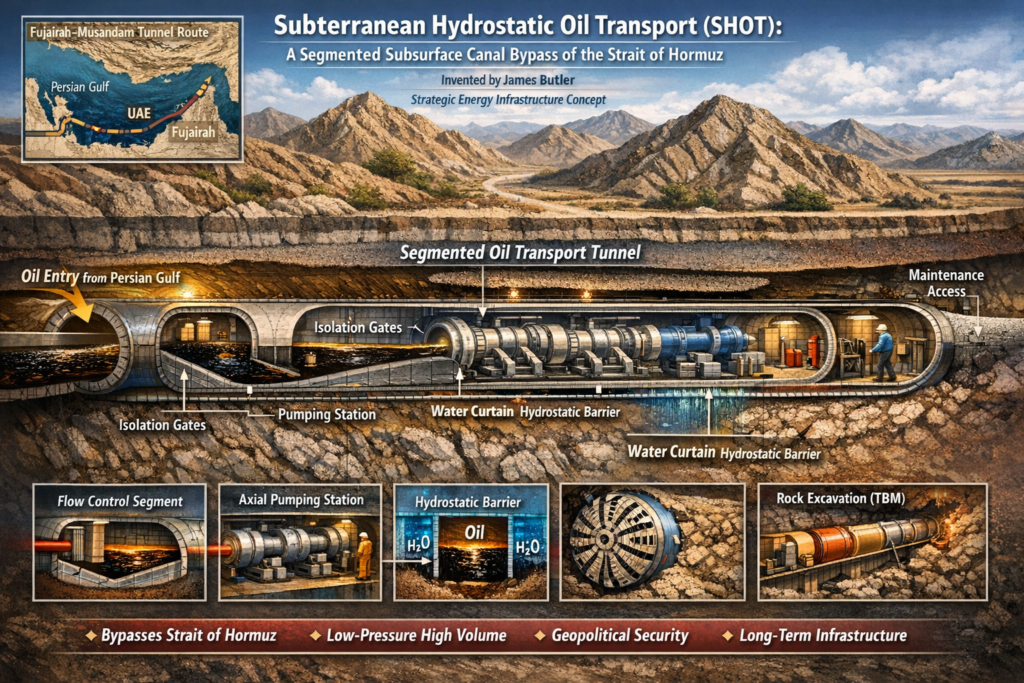
A. Segmented Canal Structure (Oil Transport Layer)
The oil transport system operates as a controlled, segmented subsurface canal:
Each segment includes:
- Flow regulation gates
- Pump-assisted transfer zones
- Isolation barriers
Benefits:
- Section-level maintenance capability
- Pressure and flow stability
- Operational redundancy
B. Asphalt-Lined Flow Invert
- V-shaped or curved asphalt channel at tunnel base
- Chemically compatible with crude oil
- Reduces friction and seepage
- Supports controlled directional flow
C. Hydrostatic Containment (“Water Curtain”)
- External groundwater pressure exceeds internal oil pressure
- Natural fissures act as inward-flow barriers
- Provides passive environmental protection
5. Best Integrated SHOT + LNG Architecture
“Energy Corridor Tunnel”
The SHOT system evolves into a multi-layered energy transport corridor, integrating oil, gas, and LNG within a single excavation while maintaining independent operating conditions.
The Strait of Hormuz crisis has revealed the limitation of every existing bypass: they remain pipelines. SHOT asks whether oil can instead be moved as a protected subterranean river.
JPB
Tunnel Zoning Structure
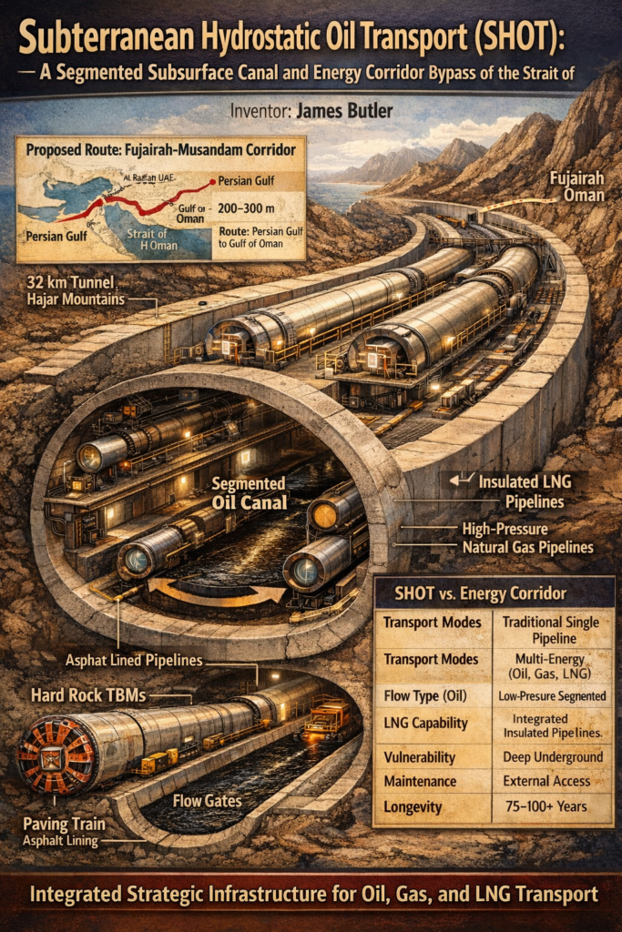
Lower Zone (Primary Flow Layer)
- Segmented oil canal
- Asphalt-lined invert
- Low-pressure, high-volume crude flow
Upper and Side Zones (Independent Transport Systems)
LNG Transport:
- Vacuum-insulated or double-wall cryogenic pipelines
- Mounted along tunnel walls or ceiling
- Fully isolated from ambient tunnel conditions
Natural Gas Pipelines:
- Standard high-pressure gas transmission lines
- Parallel routing within the tunnel
Electrical and Control Systems:
- Power distribution for pumps and monitoring systems
- Sensor networks for pressure, temperature, and flow
- Communications and automation infrastructure
System Characteristics
- Each energy stream operates in a separate controlled environment
- Thermal isolation prevents LNG boil-off and material stress
- Shared tunnel reduces total excavation cost per transport mode
- Centralized access improves maintenance and monitoring
Result
One tunnel, multiple energy streams, each operating independently within a unified structural corridor
6. Flow Dynamics and Propulsion
- Oil velocity: ~1.5–2.0 m/s
- Flow regime: controlled turbulent flow
- Movement maintained by distributed axial pump stations
Gas and LNG systems:
- Operate independently under standard pipeline principles
- Do not interact with canal flow dynamics
7. Construction Approach
Tunnel Specifications
- Diameter: 12–14 meters (expandable depending on corridor density)
- Multi-use configuration (flow, pipelines, access)
Excavation
- Hard Rock Double Shield TBMs
- Daily advance: ~10–20 meters
Integrated Build Sequence
- Tunnel excavation
- Structural stabilization
- Asphalt invert installation
- Installation of pipeline mounts and supports
- Integration of pumps, gates, and control systems
8. Operational Characteristics
| Metric | Traditional Pipeline | SHOT Energy Corridor |
| Transport Modes | Single (oil or gas) | Multi-energy (oil, gas, LNG) |
| Flow Type (Oil) | High-pressure sealed | Low-pressure segmented |
| Capacity (Oil) | 1.5–5M bpd | 5–12M bpd (scalable) |
| LNG Capability | Separate infrastructure | Integrated insulated pipelines |
| Vulnerability | Surface exposure | Deep underground |
| Maintenance | External access | Internal segmented access |
| Longevity | 30–40 years | 75–100+ years |
9. Strategic Advantages
- Chokepoint bypass: Eliminates reliance on Strait of Hormuz
- Infrastructure consolidation: Multiple energy streams in one corridor
- Security: Deep underground placement reduces exposure
- Scalability: Additional pipelines or parallel tunnels can expand capacity
- Efficiency: Shared excavation lowers marginal cost per system
10. Key Engineering Considerations
- Oil flow requires continuous monitoring and control
- LNG systems require strict thermal isolation and containment
- Structural layout must prevent cross-system interference
- Maintenance strategy depends on segmented isolation and automation
- Initial deployment may prioritize oil, with gas/LNG added in phases
11. Conclusion
The SHOT system, expanded into a subterranean energy corridor, represents a shift from single-purpose infrastructure toward integrated, multi-modal energy transport.
By combining a segmented oil canal with independent gas and LNG pipelines in a shared underground environment, the system provides a secure, scalable, and strategically resilient alternative to surface-based transport routes.
While technically complex and capital-intensive, the concept leverages established engineering methods arranged in a novel configuration to address long-term energy transport challenges.
Secure and Scalable Energy Corridor
Attribution
The conceptual framework of the Subterranean Hydrostatic Oil Transport (SHOT) system and its evolution into a multi-energy corridor is credited to James Butler.